Provides evidence of:
27/01/14
Test Model - Modelling Tools
To begin the process of creating my character in 3Ds max I began modelling a very basic version of my mech character using basic modelling techniques such as Box Modelling and other basic object modification tools and primitives. Using simple primitives and basic modelling tools such as move, rotate, scale, extrude and bridge I began planning out the basics for my model in 3D using Box Modelling and Image Planes
By starting out with a box I used the various 3Ds max modelling tools to extrude shapes out of primitive objects to create newer shapes. The principle of box modelling can also be applied to other primitive shapes.
I used more primitives such a sphere for the chest and a box for the head to create an overall body shape that i could then adjust with my reference drawings.
I also set up 3Ds max to use metric units, specifically centimeters. In the screenshots below the images showing my basic Mech character standing next to a large elongated cube was done for the purposes of determine the right scale. I typed in the scale I wanted my Mech to be in the height parameter of the box next to the Mech, this then changed its height, after that i tweaked my Mech to match the height of this box.
The reason I used metric units was so that i could model to a real world scale, and so that my work could transfer between programs if need be, and still keep the correct scale.
- Box Modeling
- Edge Flow
- Automated Symmetry
- Mesh components
- Triangle based meshes
- Quad Based Meshes
- Adhering to Polygon Limit/Low polygon Models
- Creating Primitives
- Extrusions, Chamfers, Bevels, Smoothing Groups, Vertex welding
- Hierarchies
- Pivot point manipulation
- Importing reference material, using blueprints
- Using Shaders
- Texture Channels
- Uv mapping, unwrapping meshes
- Using Splines
- Spline Modeling
- Early Rigging
- Spacing tool
- Zbrush sculpting and poly painting
- Normal map and Ambient occlusion map Extraction
- Photoshop Texture Map manipulation.
- Exporting and File Formats
27/01/14
Test Model - Modelling Tools
To begin the process of creating my character in 3Ds max I began modelling a very basic version of my mech character using basic modelling techniques such as Box Modelling and other basic object modification tools and primitives. Using simple primitives and basic modelling tools such as move, rotate, scale, extrude and bridge I began planning out the basics for my model in 3D using Box Modelling and Image Planes
By starting out with a box I used the various 3Ds max modelling tools to extrude shapes out of primitive objects to create newer shapes. The principle of box modelling can also be applied to other primitive shapes.
- In 3Ds Max I created one cylinder and then held shift and dragged to duplicate it and create another.
- I then joined those cylinders with by their faces using the bridge tool.
- Going from there i duplicated the new bridged object i created Ito form what would be the basic models version of arms and legs. joining these two objects up with additional cylinders.
I used more primitives such a sphere for the chest and a box for the head to create an overall body shape that i could then adjust with my reference drawings.
I also set up 3Ds max to use metric units, specifically centimeters. In the screenshots below the images showing my basic Mech character standing next to a large elongated cube was done for the purposes of determine the right scale. I typed in the scale I wanted my Mech to be in the height parameter of the box next to the Mech, this then changed its height, after that i tweaked my Mech to match the height of this box.
The reason I used metric units was so that i could model to a real world scale, and so that my work could transfer between programs if need be, and still keep the correct scale.
Image Planes
After modeling the Mech in a very basic form i also used my own drawn reference images to help get the right proportion.
Image planes are often created in multiple view-ports so that modelers can match up each angle of their model with 2d references precisely, but in this example i had no need to since this was my first practice model for this project.
After modeling the Mech in a very basic form i also used my own drawn reference images to help get the right proportion.
- To do this i created a plane and positioned it behind my model in 3d.
- I re-sized this plane to the exact same dimensions as the image i was about to apply to it.
- I then created a material in the material editor, and applied my drawn image to the diffuse channel, clicking on "show texture in view-port" then revealed this to me on my plane in 3D, from here i was able to alter the proportions of my model and make it more accurately represent what i had drawn.
Image planes are often created in multiple view-ports so that modelers can match up each angle of their model with 2d references precisely, but in this example i had no need to since this was my first practice model for this project.
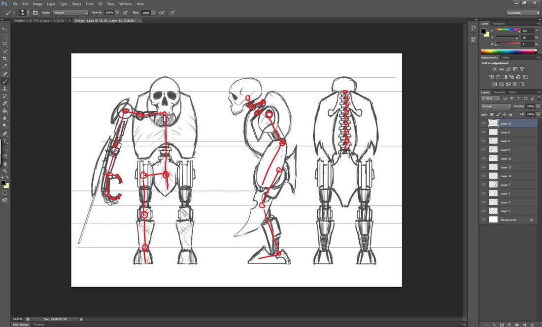
In the afternoon we were given unit 71 and 73 from our animation and rigging lecture. After describing my Mech design we went through some possibilities of how i could rig the shoulder of the Mech in maya. I also began to draw on one of my designs for my Mech to establish where the joints of it would be.
To begin some of the planning stages for these units I began drawing some simple rigging points on my character designs. The areas i drew on my model in red represent where the joints of the 3d bones would go.
After going home I found a very helpful tutorial that allowed me to solve a problem i had this afternoon to do with rigging pistons, i decided to use 3Ds max for this project due to my familiarity with it, although i understand that using different pieces of software is necessary i wanted to produce the best work i could in the short amount of time i had to complete the project, i know that i can certainly produce a better end product in 3Ds max.
29/02/2014
Mech Character Model Creation
After doing some research on the methods i will be using and creating a basic test model i began modeling what would eventually be my actual final Mech character in 3ds max.
I used various different modeling techniques to create my Mech inside of 3ds max.
Here i will go through all of the processes i used to create my character
As shown in the above images, I decided to first tackle the problem of the pistons for my character. Following the YouTube tutorial i mentioned earlier in this post. My first attempt to create the piston is shown in the slideshow above, it unfortunately did not work completely and due to my over complicated way of modeling the pistons i had undesirable stretching effects.
In the below images you will find my completed successful piston rig.
In the below images you will find my completed successful piston rig.
- I started by using cylinders to create the shapes for the pistons, i used the Chamfer tool to create the slanted edge of the larger piston.
- The two spheres were just made as primitives and they act as dummies for the pistons to look at and follow in the rig.
- Using the Align tool i accurately positioned the pivots to the top and the bottom of the pistons, without aligning the pistons properly the rig would not work, this was the mistake i made in the first attempt.
- After i had correctly modeled the pistons and re positioned their pivot points i linked the objects together in a specific order.
- i used the look at animation constraint to tell the piston objects to look at the spheres and follow their rotation, this gave the desired effect of making hydraulic pistons.
After i had created the piston rigs and found out that the completed rig can even be copied and pasted and re-positioned i began modeling the rest of my mech.
I created the piston to try to create an interesting sense of mechanical movement with the character, I felt that the pistons helped give aesthetic interest to the model.
The next thing i modeled was the basic inner chest piece, i modeled this using basic Box Modeling Techniques since this will be a small part of the character that will not be seen as much as other areas.
The only tool i actually used in the creation of this piece was the chamfer tool, i used chamfer to create a piece of geometry that the pistons would attach too, this object would be inside of a larger chest cavity. I also moved some vertices around with the move tool.
As seen in the images below, i was going to create some triangular pieces that would serve to guard the piston joints but i decided to remove them as they did not look aesthetically pleasing.
2/02/2014
Today I continued the modelling process of my Mech in my spare time.
After the inner chest object and the pistons were created i then tackled the arm.
The limbs of a mechanical character are quite difficult to design since their range of movement ideally should be similar to that of the organism the mechanical character is based off in real life. My character being bipedal this would be a human, i knew i would need to have a shoulder join that rotated in two different directions, and also an elbow joint as well as arm with a rotating motion.
In the images below i have documented my modelling process of the shoulders and arms.
Also seen in the images is a protrusion in the outside of the shoulder, this was meant to be a feature i modeled in so that i could later attach the armour plating, it was then taken out due to it not being in the correct place, i noted the armour would have to attach to the arm itself otherwise it would not be able to rotate with the limb and would clip through the model.
Today I continued the modelling process of my Mech in my spare time.
After the inner chest object and the pistons were created i then tackled the arm.
The limbs of a mechanical character are quite difficult to design since their range of movement ideally should be similar to that of the organism the mechanical character is based off in real life. My character being bipedal this would be a human, i knew i would need to have a shoulder join that rotated in two different directions, and also an elbow joint as well as arm with a rotating motion.
In the images below i have documented my modelling process of the shoulders and arms.
- I began with a simple box and chamfered its edges with added segments to round of the edges and create a different shape, this will be the housing of the insertion of the piston joints.
- I then extruded another round shape from the first one to create an axis for the arm to rotate on.
- I then moved on to the creation of the arms
- I began with simple cylinder primitives and converted them to editable polygons.
- I then duplicated them and attached them using the attach tool.
- One they were all one object i was able to use the Bridge tool to join them together geometrically.
- After the basic shape of the arms were created i noticed i need to edit my shoulder object to give the mech a free-er range of movement in the area that is its shoulders, this next process also looked aesthetically pleasing on the model.
- I used more cylinders and simple modelling techniques to edit the shoulder as seen in the images below.
- once the entire shoulder piece was complete i duplicated the piston and added the second one to the back of the inner chest piece and positioned them in the housing i created in the shoulder.
Also seen in the images is a protrusion in the outside of the shoulder, this was meant to be a feature i modeled in so that i could later attach the armour plating, it was then taken out due to it not being in the correct place, i noted the armour would have to attach to the arm itself otherwise it would not be able to rotate with the limb and would clip through the model.
After finishing the first pass for the shoulder joint i moved on to creating the arms and the large chest like main armour plating of the Mech.
Using the same techniques i have previously discussed such as duplicate, bridge, and chafmer i began creating the arms for the Mech taking into account all of the areas that would rotate or move.
To create the chest:
The arms, and the rest of the model was deigned in a way where each joint could actually rotate around each other joint as if this was a real mechanic thing. I made sure that none of the rotations of the joints clipped through eachother to give a sense of realism in the model.
Using the same techniques i have previously discussed such as duplicate, bridge, and chafmer i began creating the arms for the Mech taking into account all of the areas that would rotate or move.
To create the chest:
- I started with a sphere and lowered the polygon count so i didn't use too many
- I then removed the top and bottom two rows of polygons to create a barrel shape.
- I also removed the back of the sphere so that i could expose the spine of the Mech when that is created.
- After that i added an FFD modifier, this allowed me to easily manipulate the shape in a more general sense, i matched the reference image i had open as closely as i thought was necessary.
- I then used soft selection to more finely manipulate area of the object, soft selection allows you to select one vertex and have the others in a specified radius be influenced by that movement.
- Finally once i had the shape i wanted i added a shell modifier to give the polygons of the sphere a thickness, the resulting object looked how i intended.
The arms, and the rest of the model was deigned in a way where each joint could actually rotate around each other joint as if this was a real mechanic thing. I made sure that none of the rotations of the joints clipped through eachother to give a sense of realism in the model.
03/02/14
The imported skull problem
The first thing I did today was to import my Skull model into 3Ds Max, into the same scene as my main Mech model. To display my model to a high quality in 3ds i max, i first imported the low poly Skull model into the software, I then created a Material and added my Diffuse map (colour texture information) from Zbrush, and my normal map (Surface detail and model form information)
3Ds max requires some settings to be changed to display normal maps in properly, the main thing being the Gamma and LUT settings. To display normal maps Gamma and LUT correction needs to be turned off in the render settings.
Although i has set all the settings properly to my knowledge, I was getting a very bad looking render. I had no idea why this was happening so i consulted the world wide web and figured out that i needed to reset the Xform which was a button under the objects utilities tab in 3ds max that i did not know about, it became apparent that this button needs to be pressed often when objects are imported into 3ds max from external software since.
The below screenshots show the problem i had and then the fixed result.
Modelling the Neck Mechanics.
To model the neck of the Mech i used a very similar process to that of the arms in the test model. I wanted the neck to have some range of motion but i know that it did not require allot of movement. Here i have annotated screenshots showing my modelling process.
To model the neck of the Mech i used a very similar process to that of the arms in the test model. I wanted the neck to have some range of motion but i know that it did not require allot of movement. Here i have annotated screenshots showing my modelling process.
I also modified the area that the pistons attach to on the model as seen in the annotated screenshot below. I did this to create a more grounded look to each piece, instead of just having the ball joint covering just floating attached to the chest.
Remodelling the Inner Chest
After getting further into the modelling process i noticed that the inner chest would be seen from various angles and i wanted to change it so that it looked more visually interesting.
Using box modelling and the shell modifier I created a inner chest that roughly resembles a rib-cage, this made the angles where you see through the Mech's main chest plate look allot more aesthetically pleasing.
I have annotated the screenshots to describe my modelling process in detail.
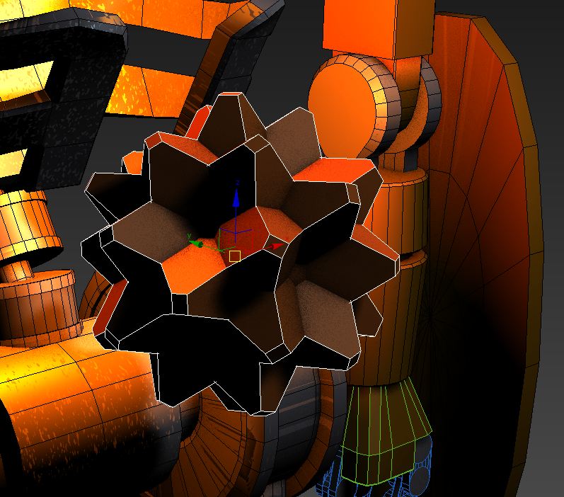
I also added this primitive object into the middle of the inner chest to act as the core or power source of the mech, when animated this core will slowly rotate and glow, it will appear to light the whole model from the inside. The light was added to the mech to give a sense that the inside of the chest is the source of the mechs power, a scene I have planned is one which shows the mech "powering up" as the core rotates and glows over time until the mech is able to stand up.
Modeling the Pelvis and Legs
To model the legs i followed my connect quite closely, i did however have to make some changed to make the joints work more realistically. Here i will demonstrate how i did this with annotated screenshots of the process.
To model the legs i followed my connect quite closely, i did however have to make some changed to make the joints work more realistically. Here i will demonstrate how i did this with annotated screenshots of the process.
08/02/14
Modeling the Spine
Here i will demonstrate with screenshots the modelling process i used to create the spine for my Mech character.
Modeling the Spine
Here i will demonstrate with screenshots the modelling process i used to create the spine for my Mech character.
Modelling the Hands
Here i will show how i modelled the hands of the Mech.
Here i will show how i modelled the hands of the Mech.
Project Modelling Milestone
I have now reached an important milestone with my modeling process. As shown with the image below i have Modeled the majority of my mech character and even have already rigged some parts such as the shoulders.
From this point going forwards all i have left to do with the modeling process in 3ds max is to:
Once those things are done i can move on to texturing my model and creating Normal maps for them.
From this point going forwards all i have left to do with the modeling process in 3ds max is to:
- Optimize, ( Reduce polygon count if possible )
- To UVW map each object in the mesh.
- Add any finishing touches to the model.
Once those things are done i can move on to texturing my model and creating Normal maps for them.
Modelling the Blades
Here i will describe the process of creating the blades for my mech using splines and my concept art.
Here i will describe the process of creating the blades for my mech using splines and my concept art.
The blades were not directly shown being used in the final trailer because I did not want to show violence around the national trust site.
21/02/14
Additional Model Tweaks
Before moving on to the next stage of production i decided to update my model more and optimize it (reduce the polycount) To do this i used all of the methods i have demonstrated previously, including simply re-sizing different areas of the Mech and editing certain pieces to look more appealing.
Creating UV maps for my model
23/02/14
Creating UV maps was something that I prior to making this model had little experiance in doing. Tonight i taught myself through the use of the internet how to properly use the tools in 3ds max to unwrap 3d models and create UVs for them.
A UV or UVW map is the 2D image co-ordinates that transfer 2D images on to 3D objects. As of today this is the most industry practied method of texturing 3D objects. Without a UV map the algorithms inside a 3D package has no information on where to display 2D images on 3D objects, with a UV map the co-ordinates are presented to the algorithms and then the 2D image can be displayed correctly on a 3D object.
3D models (unless primitives) do not come standard with UV maps, they have to be created, the process of creating UV maps is like turning the 3D object into a 2D image. Each part of the 3D object must be unwrapped and flattened out into 2D space, and all of the flattened parts of the 3D object must be organised into a UV tile, this tile is the thing that will allow the software to apply 2D images to 3D objects.
There are 2 ways to give an object UVs, a quick and simple way which does not give the artist very much control as shown below:
To have professional industry standard UVs on a model it must be unwrapped by hand. This process is very time consuming on complex models but it will result in me being about to have precise control over the surface of my model. I will now demonstrate using screenshots the UVs i created for each and every part of my model.
Below are some shots of my Mech with a checker pattern applied to demonstrate that every single piece of the Mech has been fully unwrapped by hand.
Sculpting Normal Maps
The Arm Shields
To create the normal maps for different parts of the Mech i had to sculpt them in Zbrush to generate normal maps. I did this in the same way I sculpted and textured the Skull and the Robin.
To begin with i exported the model for the arm shields i created in 3ds max in the OBJ format, i was then able to import this into Zbrush to create a high poly mesh from this low poly model.
In the video below I show the process of sculpting and texturing the arm shield models, to create a damaged worn look to the arm shields i used the slash tool to create deep scratches as well as applying alphas to the surface to create the look of rusty worn metal, i did this to quite a extreme extent and then used the morph tool to dial back some of that intense detail to create variation among the surfaces.
When painting the arm shields i wanted to keep it quite subtle since i will be making most of the metal effects with the shader, I used alphas from Zbrush Central of metal rusty textures and applied them in various colours all over the model to create a variation in the surface colour.
After sculpting and painting the arm shields i exported the Diffuse map from Zbrush and also exported a high poly and low poly version of the arm shield mesh, I then plugged those meshes into Xnormal and Exported Normal maps and ambient occlusion maps to later use in 3ds max.
The Chest
To sculpt the normal maps for the chest i used the exact same method i described for the arm shields, I wanted these two pieces to look like they were made and worn down in the a similar way, so the sculpting process was pretty much incidental. I used the same technique of wanderings the model down and then morphing it back so the damage is more subtle, and even used the same brushes and alphas.
To sculpt the normal maps for the chest i used the exact same method i described for the arm shields, I wanted these two pieces to look like they were made and worn down in the a similar way, so the sculpting process was pretty much incidental. I used the same technique of wanderings the model down and then morphing it back so the damage is more subtle, and even used the same brushes and alphas.
Exporting & File Formats
When exporting my files from 3ds max I made sure the object were Uv mapped and then I exported than as an OBJ. The OBJ file format is an almost universally compatible file format for 3D objects, It contains the vertex coordinates of the 3D model you export and can also be embedded with material and UVW texture coordinates so that those things can be accessed in other programs. Making sure the model had UVs before I exported it was essential because without them I would not have been able to generate normal maps from the high poly sculpts I did, nor would I have been able to generate texture maps.
After the sculpting is finished the models are exported from Zbrush as OBJs, a Low polygon and High polygon version of the model is exported so that the low and the high version can be used in Xnormal to generate normal and ambient occlusion maps.
After the sculpting is finished the models are exported from Zbrush as OBJs, a Low polygon and High polygon version of the model is exported so that the low and the high version can be used in Xnormal to generate normal and ambient occlusion maps.
Creating Materials in 3Ds Max
After i had generated maps from the Zbrush sculpting and painting it was then time to use those maps on the UV-ed models in 3Ds max, to use the maps i created i would have to create custom materials in side of 3Ds max.
My goal for the main armour material of my mech was to create a golden bronze style of metal, a metal which looked old and worn with age, this is why i sculpted it in the way that i did and for the material to compliment this i looked at various references to achieve the effect i wanted, the process of creating this look is documented below.
The diffuse maps from my poly painting in Zbrush on their own would look quite flat, so i combined the diffuse poly painted map with the ambient occlusion map i exported from Xnormal, this gives the object some baked in shading and generally makes the texture look more believable and realistic on the 3D model.
After sorting these maps out in Photoshop i then go on to apply them to the model in 3ds max.
The exact same process was repeated for the chest part of my mech.
Creating tiled textures
In the brief it is noted that a maximum of 5 textures are allowed on the model, I have already used up three with the custom made textures for the skull and armour plating of the chest and arms, this left 2 textures that I could create to be tiled along he remaining areas of my mech.
To create these textures I went to www.cgtextures.com and looked for some metal textures that fitted with what i wanted for the surface of my mech, I continued with the golden bronze hammered metal look and found some textures that fitted in with that style.
I then used Photoshop to manipulate them and create tiled textures using offset. It was important that none of the textures had large amounts of shadow on them because that would then show up as very flat when applied to a 3D object. To remove the shadow i used the shadow and highlights tool to make the image look flatter, this flatness would then be resolved when i added normal maps. After i has manipulated the image and used offset to make it tillable i then had to get rid of the seams that offset created, i used the clone brush and the spot healing brush to do this.
Once the diffuse colour map was finished i then created the specular map, the specular map controls the colour and frequency of the reflective quality of the surface of the texture, because i wanted the texture to reflect a bronze like colour i made the specular map the colour i wanted the specular highlights to be.
After the diffuse and specular maps were created i then created the height map which would then be turned into a normal map with Xnormal.
To create the height map i made the image black and white, in height maps the whiter the colour in the map, the more raised that area will be and the darker the colour the lower it will be on the object it is applied to.
When i created my grey scale height map i noticed that the insides of the hammer marks on the bronze texture i used had allot of white in them and would therefor appear raised when that is not necessarily ideal for the texture, so i meticulously edited the map by hand covering up and white inside areas with a grey colour.
Once this height map was created i then put it into Xnormal and generated a Normal map from the height map.
Texture Sizes
When creating textures it was important that I saved them in a resolution which was in the power of 2. The most commonly used texture sizes are 512, 1024, 2048 and 4096. The reason they had to be kept as powers of 2 was because of the cross platform consideration of if the textured objects were going to be taken in to UDK. Real time environment pipelines often work better when textures sizes are kept in the power of 2, it makes applying textures and tiling them much simpler.
When creating textures it was important that I saved them in a resolution which was in the power of 2. The most commonly used texture sizes are 512, 1024, 2048 and 4096. The reason they had to be kept as powers of 2 was because of the cross platform consideration of if the textured objects were going to be taken in to UDK. Real time environment pipelines often work better when textures sizes are kept in the power of 2, it makes applying textures and tiling them much simpler.
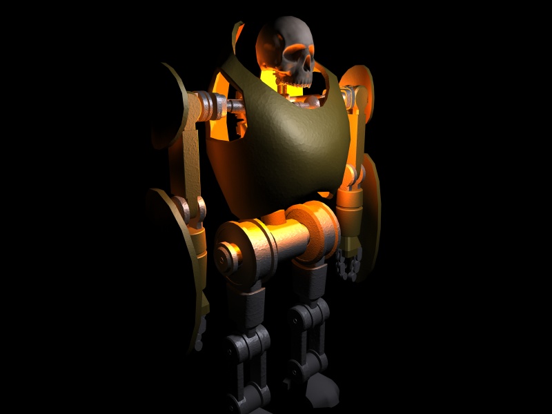
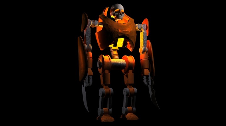
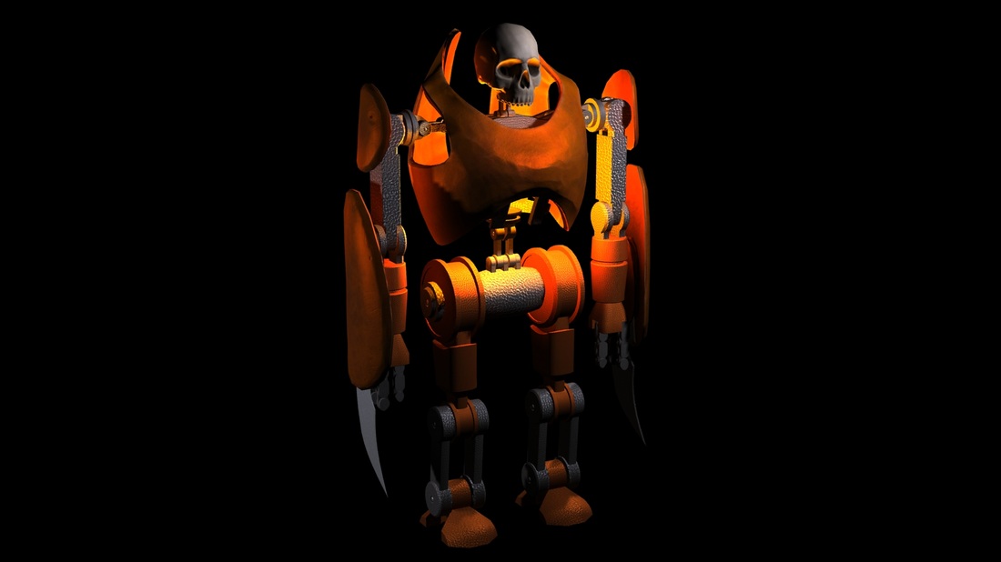
Modeling and Texturing Complete
Below is my fully textured Mech rendered in 3Ds Max, I also added Material IDs to my mech to better organised my materials
At this point, the modeling and texturing process is completed.
At this point, the modeling and texturing process is completed.
Rigging
Rigging the model was the next thing i did, this is the area I had the least experience in and it has been the most difficult part of the project for me so far, as seen in the following documentation the model had to change quite allot sue to time constraints and problems that i had when rigging.
The first method of rigging i tried involved creating an bones and an IK solver for the spine and using custom made controllers for the rest of the limbs. I managed to get the IK solver working on the spine and i even cleaned up the weighting issues i was getting while using the skin modifier (The skin modifier binds geometry to bones to create mainly organic rigs) but the main problem came when trying to create the controllers for the other limbs, moving the spine would leave the controllers for the other limbs behind no matter what i tried to do, i tried using all kinds of constraints to get them to properly stay in position when the spine moved but i could not find a way to do it and it was costing me time.
I spent a few days trying to fix this problem and i found no way of fixing it. The other major reason this method did not work was because the pistons i had created completely lost their function then the spine was moved.
Below are some images of the process of me trying this method:
After much deliberation i deiced to re model some of the areas of my Mech that were causing me problems, i decided that wasting any more time fixing them would be detrimental to the project so instead of dwelling on these problems i created new joints for the Mech which would be more easily rigged.
In the end i think that it turned out looking much better than the previous design, i think the new joints i created look much more believable then the pistons and spine i used before, the previous spine and piston configuration actually fit in less with the time scale and setting of my trailer since hydraulic pistons and complex robotic spines would not have been possible in that time, although the mech is powered by a magical energy source i still wanted to ground some of the design in reality.
Successful Rig
I began by grouping every single major component into the logical groups on the Mech's body and adjusting their pivot points so that they match with the rotation points of the limbs
The legs were not grouped since I created an IK system for them which is explained in the below images
After all the pivot points and IK system were in place the mech was ready to animate.
Below is a quick animated i did for the rig to test its range of movment, the purpose it to take the limites of each of the limbs to their extreams without clipping.
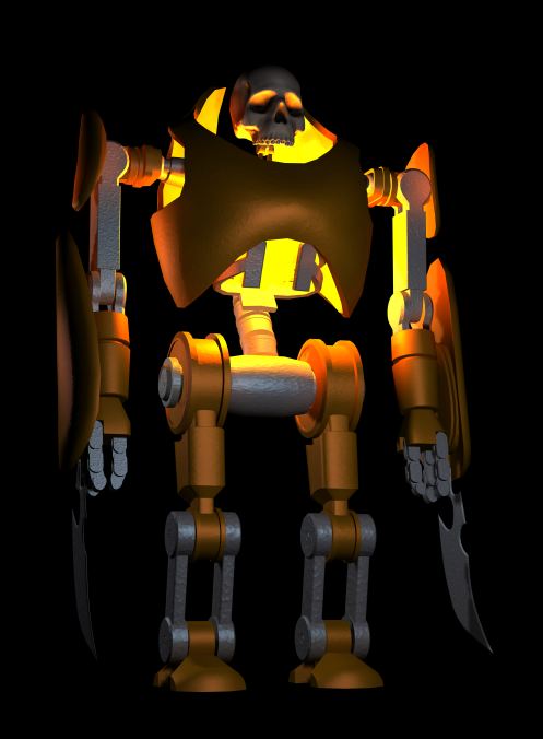
This is my newly altered Mech model.
Below is a quick animation i did with the rig to test the Mechs range of motion.
Creating and wiring Custom Parameters
- Core Rotation
Because i wanted to have a constantly rotating core to signify the magic that powers the Mech character I had to create my own custom controls to affect the rotation of the core of the Mech.
A Parameter in 3ds max is a UI element that usually uses a 0-100 slider, they are used on everything including the commonly used extrude and chamfer tools.
I will be creating my own custom parameter that i will then wire to X axis of the rotation of the Core in my Mech, I will then make it so that the 0-100 slider corresponds to the speed of the cores rotation.
Below is a video showing the result.
